Serial # 7-M-3796
In January 2007 I took advantage of an opportunity to get one of these
mills for free. Cleaning & prepping the machine delayed a
number of projects, but its in fine shape and I'm looking forward to
getting it running.

I eventually got it to the patio, removed the table & motor;

My dad came over to help, we got the mill over onto its back, then down
the ramp into the basement. The casting is blocked up with a
length of 2x4, keeping the back end of the spindle from bearing on the
sled.


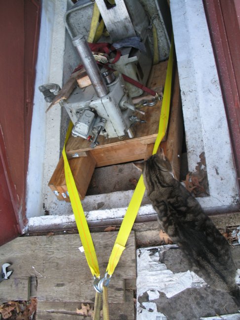
And down, safe & sound!

Then after a week of stripping & cleaning;
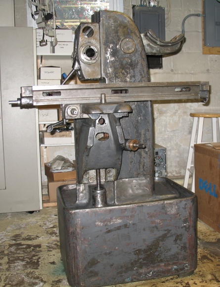
Nichols made several versons of the head, here's a closeup of mine;

February 2007, now painting;


Paint is Sherwin Williams "Hyper Blue". Two coats were applied,
with the addition of an alkyd enamel hardener. 32oz is about
right
for the mill. The paint hides brush strokes relatively well but
tipping the coat about an hour after application helped the finish
considerably. Overall I'm quite happy with how the paint worked
out- it makes the other machines seem drab rather than
understated. We'll see how it stands up to oil & chips.
The Nichols manual specifies "600-W" oil for all the zerks, in this
case
its not viscosity but the name of a manufacturer's brand. Another
Nichols owner traced to an approximately ISO 350 lubricant. I
bought some ISO 220 grease for the spindle, I tried it out, and it
works
fine but makes a mess when the excess is flung clear- so installing a
guard around the pulleys will avoid laying down a racing stripe on
neighboring items. I switched to Vactra #2 on all the sliding members
which is lots easier to clean up.
My mill has the 5-groove pulleys and uses an A59 sized belt.
The motor gearbox was dry but drained clean when flushed with WD40. The
manual mentions a "dipstick" for checking the oil level in the motor's
gearcase, if the tag shown in the manual is missing, the dipstick is
easily found. Locate the air vent between the motor & gearbox. When
facing the output shaft with the vent upwards, the dipstick is the
small
screw seen on the left of the mouth of the vent. There is a gearcase
vent on the right of the mouth. Both are unscrewed for their respective
service. The vent on mine was painted shut, a soft wirewheel cleaned it
right up. I have some DTE Heavy/Med gear oil in there now, which
is thinner than the specified 40W Motor oil- I will get the proper
stuff
in there shortly.
In operation, some oil drips out around the gearcase shaft, so moving
the pulley out 1/8" or so will let it drip clear and not be flung all
over creation. 40W oil is a definite improvement over the DTE in this
case.
I mounted the vfd's speed control pot in the start/stop cluster, should
make tweaking the speed handy.

This shows the jury-rigged vfd & power. The drum switch
connects to the vfd's fwd/rev input. The toggle connects the vfd
output to either the aux outlet or the Nichols motor. The lower
box contains a transformer, diode bridge and relay. The start
button latches the relay on, stop turns it off. The latching
relay
connects the fwd/rev circuit through to the vfd. So, the
start/stop, fwd/rev and speed control work for the aux outlet and the
main motor.

I put the R head onto the mill for a motor & bearing test;


The R head is a bit too big for the mill, it takes up a good deal of
the envelope and is clumsy to tram. A smaller head would be a
better fit, though an R or M head will certainly work.
4/1/2007
Threaded flange for the y axis nut- the bronze acme nut will thread
into this & be soldered into place, then everything will be turned
& faced to size.

I did the flange first so I could do all the work on the nut in one
setup.
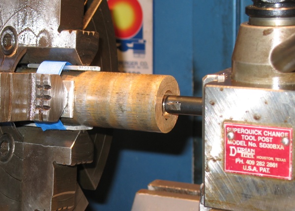
The nut is SAE660- it turned wonderfully. Its a welcome break
from
various bits of mystery metal- one of which I made the flange
from. The step on the nut is an extra .020" finishing allowance
after the flange is screwed on & soldered.

I didn't nail the threads exactly but the fit is pretty good. The
visible face here will be removed by the finishing passes. I
sucessfully single-pointed the internal acme threads (10tpi), using the
y axis screw as a go/no-go gauge.

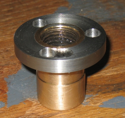
Showing nut turned for OD w/ grease groove, and flange turned and faced
after soldering. You can see the little band of solder right in
the joint between the bronze & steel. The sludge in the acme
threads is some grease I wiped in to make sure the solder didn't wick
inside.

Parting was nice and smooth.... :)

And here all nice & pretty, looks good so far huh?

And heres what happens when you don't snug the jaws down tight enough
on the dividing head... Only a cosmetic problem, but a drag
nonetheless. Because I lost zero I had to increase the clearance
on the 3rd hole..
And here a test-fit on the y axis screw...

And here, installed. The y axis feed feels quite good. I
think I succeeded in a centering fit, there is no discernable backlash
either. Cosmetics aside I'm quite happy with the new nut.

June 2007
In April myself and two others went shares on a Nichols parts machine,
it took me a while to get their parts shipped out. A minor point
I'd like to stress- when going shares on a parts machine, negiotiate
both the shares of the purchase price and the shipping.
One of my parts was an overarm support. Its an older one with
bronze bushing that was badly wallowed out. I replaced it with a
steel plug bored true to the spindle, into which I'll fit a needle
bearing.
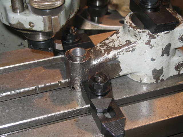
The support clamp is loose on the overarm so it slides as the table is
moved inwards, making the boring head cut the bushing true to the
spindle. It would've been better to push the overarm with an
angle plate, or clamp the support and let the overarm slide, but there
wasn't room to do either.

And a picture of the daughter, taken one evening we spent in the
basement;

Here I finally got to finishing the front face of the arbor
support. Naturally I discovered I left the bore .0015 or so too
small, so at some point I'll have to try and replicate the setup...

12/2007, 1/2008
I had an occasion to repair a Nichols knee gib that was cracked in 3
places. I milled about 1/8" off the back of the gib and fit a strip of
steel of similar thickness. I put a screw in on each side of each of
the 4 bolt holes. Worked like a champ, and the gib is in service now.
There appears to be some tendency for knee gibs to break around the
middle two bolt holes, perhaps due to excessive tightening of the knee
lock.

Having gotten the gib figured out, I reassembled the machine and did the
first job on it. In this case, cutting away the bulk of the webs on an
inexpensive import angle plate. I made a movie of the finish cut on one
of the webs here;
nichols-lever-feeds.mpg
Here's a 5" diameter shell end mill by P&W, very nice- unused, a
bit of surface rust in spots due to poor storage, looking forward to
trying it sometime;

;;; eof